|
|
 |
|
|
A Tale of Two Tigers: Part Two
 |
A Tale of Two Tigers: Part Two
Putting Your Money Where Your Mouth Is
with Blake Coster
In part one of A Tale of Two Tigers, I outlined my plan for modelling the plastic Tiger I E. Now it's time to put my money where my mouth is and show you, the reader, the techniques and methods I'll be employing to achieve the desired results.
So gather your hobby tools and let's get started.
|
| Before I get into the fun stuff of detailing the Tiger I E, we need to complete some basic assembly first. Luckily, I prepared this early; a handy video assembly guide for the plastic Tiger I E. |
| How To Assemble The Tiger I E |
| Basic Assembly |
| As you can see below, I have completed some basic assembly of my Tiger I E. I have only partly assembled the model into subassemblies, to make it easier to work on the components separately before completing the final assembly. |
A Job Two-thirds Done
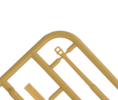
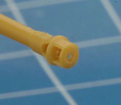
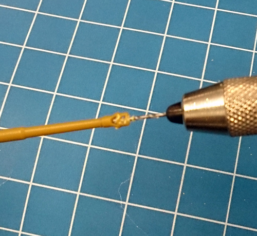
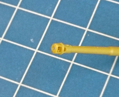
Straight out of the box, two-thirds of the muzzle brake on the 8.8cm main gun of the Tiger I E has already been drilled out. That just leave us the final third to complete. This can be done in three easy steps.
Right: The 8.8cm KwK 36 L/56 barrel on the plastic sprue.
Far right: A close-up of completed barrel. |
 |
 |
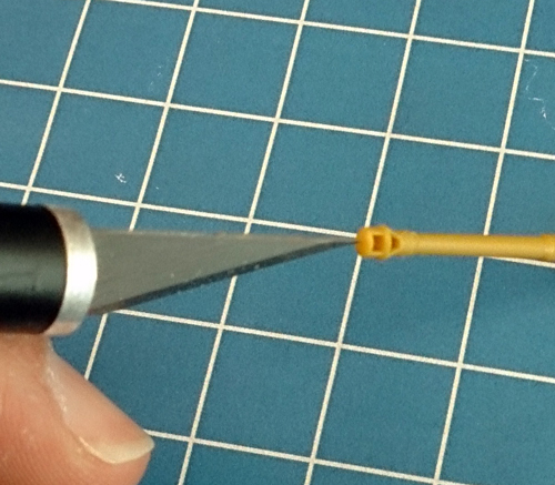
| Step 1. With the tip of my hobby knife, I prick the centre of the muzzle brake where I want the hole. |
Step 2. Using a pin vice and the appropriate sized drill bit, I carefully drill out the muzzle brake. |
Step 3. The completely drilled out muzzle brake. It's small details like this that will make our Tiger I E look great! |
 |
 |
 |
 |
 |
On The Air Waves
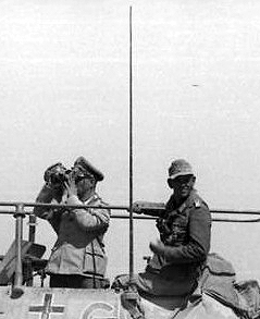
Like all German tanks during World War Two, the Tiger I E was equipped with the Funkgerät (or FuG) 5 radio set. This radio was used for all tank-to-tank communication within platoons and the company.
Lucky for us, the FuG 5 radio set had an antenna two metres in length; making our job re-creating it to scale for Flames Of War (1:100 scale) relatively easy.
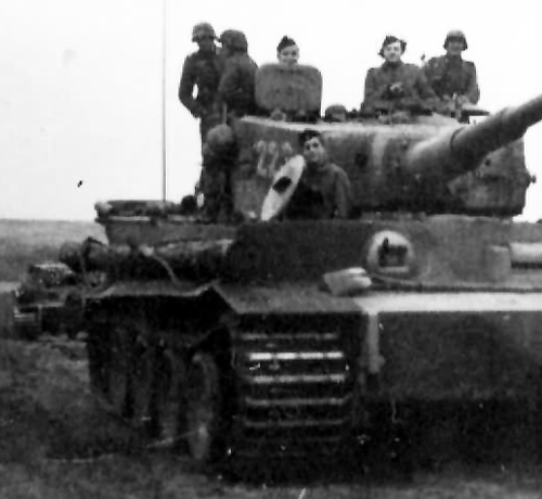
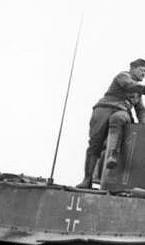
Left and far left: Examples of an antenna of the FuG 5 radio set on a Tiger I E. |
In the past, I've used a bristle from a brush to model tank antennas but while this a quick and easy way it doesn't re-create the tapered look of the actual antenna FuG 5 itself.
Instead, I'll be using a method from scale modelling days to help create this look. So let's take a look at this method below.
Right: A close-up of a FuG 5 radio antenna showing it's tapered shape. |
 |
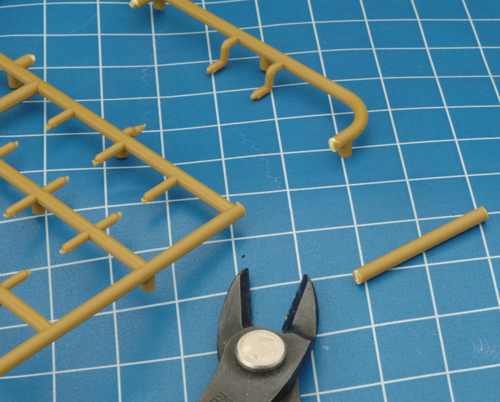
| Step 1. First, I cut a piece from the outside of the frame from the plastic Tiger I E sprue. |
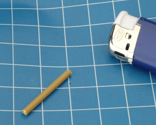
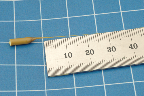
Step 2. Next, using a lighter, I carefully apply heat to the centre of the plastic rod and as begins to melt, I pull the two ends apart to create a thin plastic string. This will quickly cool and become the basis of our antenna. |
 |
 |
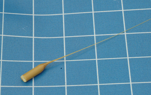 |
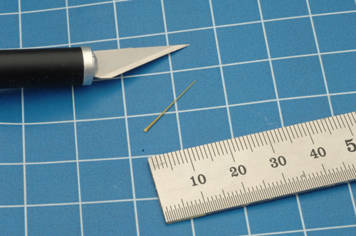
| Step 3. Using the natural taper created by the melting and stretching of the plastic, I then cut the antenna to length (20mm). |
 |
 |
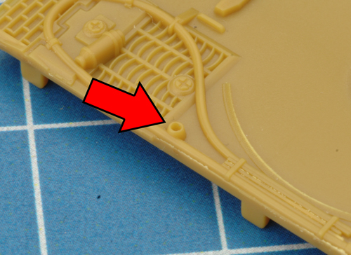
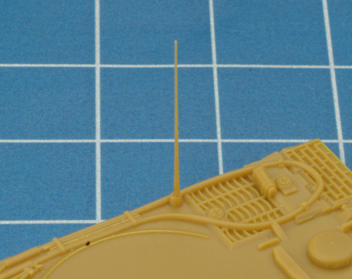
| Step 4. Finally, I attach the antenna in its correct location on the deck of the Tiger I E. |
 |
 |
 |
Those Pesky Jabos!
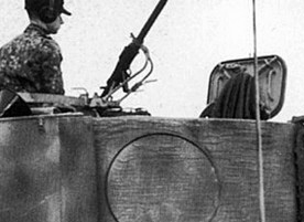
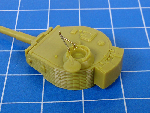
German tanks were equipped with a device called a Fliegerbeschussgerät which consisted of a tubular metal frame that could be clamped to the cupola ring. A machine-gun could then mounted to it in order to provide a basic defence against enemy aircraft.
The Fliegerbeschussgerät was only employed when vehicles were on the march usually behind the front lines when the chances of encountering enemy ground units were low and the risk of strafing aircraft was high.
Left: The Fliegerbeschussgerät fitted to the turret of a Tiger I E. |
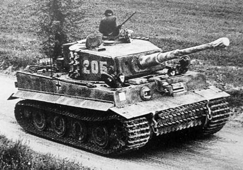
The downside of the system was the machine-gun used with the Fliegerbeschussgerät had to be taken from the vehicle; the hull machine-gun was used as no spare weapon was issued to act as a dedicated anti-aircraft defence.
Right: A Tiger I E on the march with the Fliegerbeschussgerät fitted. Note the missing hull machine-gun. |
 |
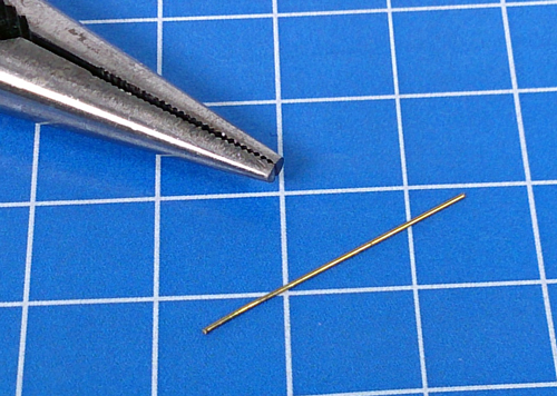
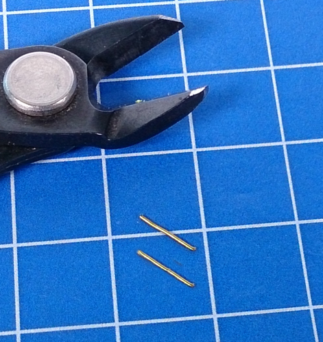
| Step 1. I begin by cutting two 1cm pieces of brass wire in an appropriate gauge. |
Step 2. Next, I make a 90-degree bend to one of the ends. |
 |
 |
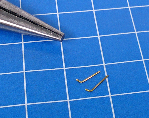 |
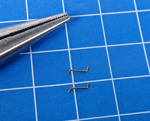
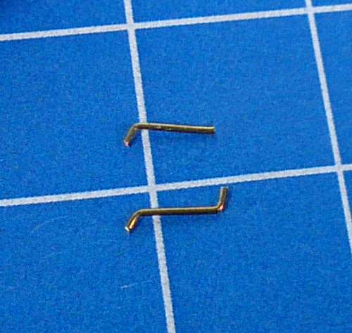
| Step 3. I repeat this process to the other end but in the opposite direction. |
Step 4. I then clip the end from one of the pieces of wire. |
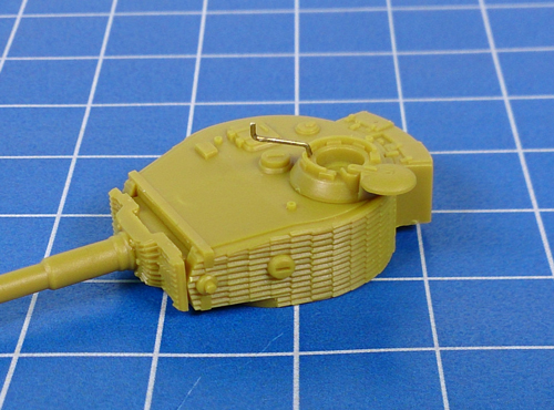
Step 5. Next, I attach the two-bend piece to the inside rim of the turret cupola. |
 |
 |
 |
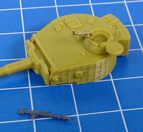
| Step 6. I complete the my Fliegerbeschussgerät by angling the second wire piece to match. |
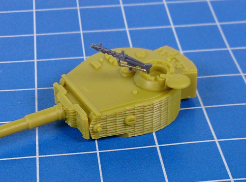
Step 7. I then attach a spare MG34 that I had left over from a plastic Sd Kfz 251 half-track sprue. |
 |
 |
 |
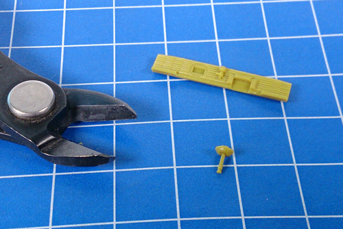
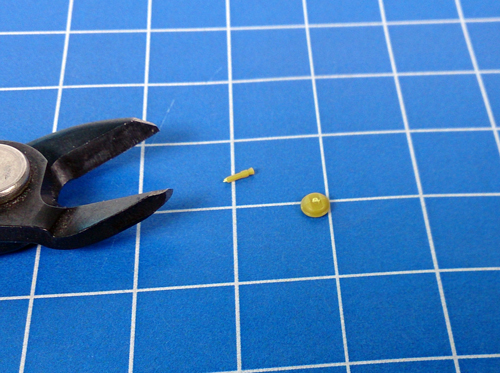
| Step 8. To complete the look of the Fliegerbeschussgerät, I clip the hull machine-gun barrel from its mount. |
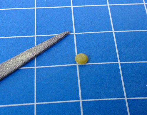
Step 9. I then remove any leftover barrel with the edge of a hobby file. |
 |
 |
 |
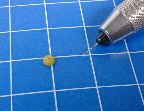
| Step 10. Finally, I use a pin vice to create the empty machine-gun port before attaching it to the glacis plate. |
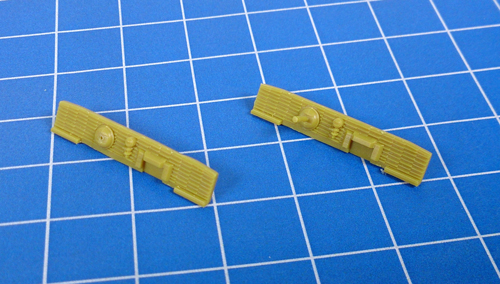
Below: Two glacis plates. On the left, without the hull machine-gun and with the hull machine-gun on the right. |
 |
 |
| Turret Detail |
| Let's now add some detail to the turret of our Tiger I E. |
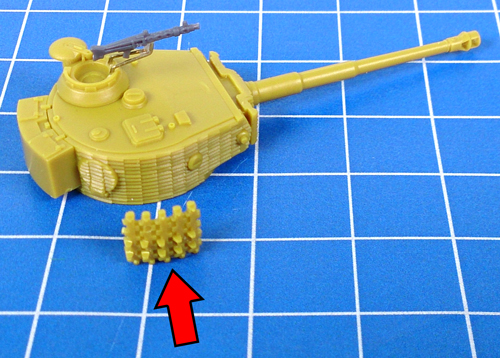
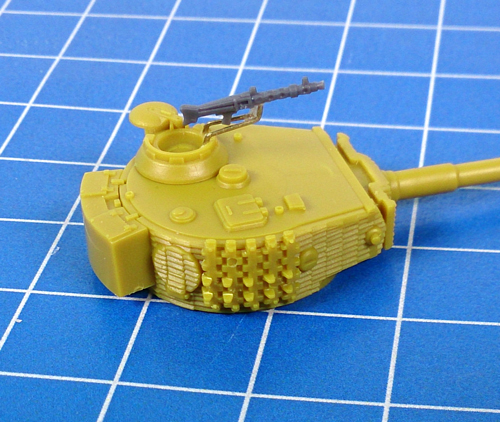
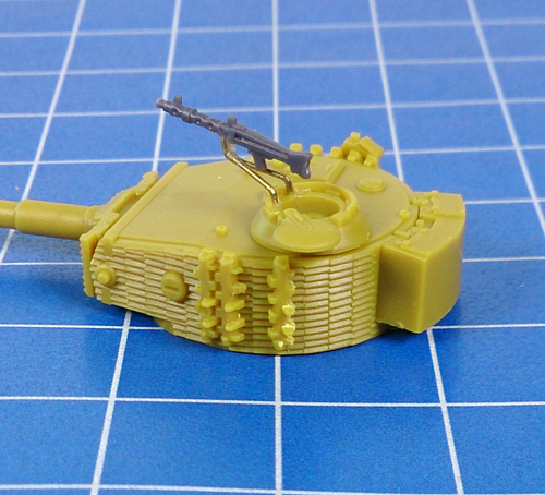
| Step 1. I begin by attaching the spare track links to the right-hand side of the turret. These are easy to align as they fit perfectly between the rear escape hatch and vision port. |
 |
 |
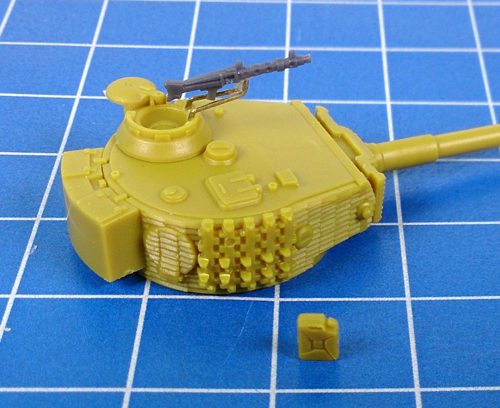
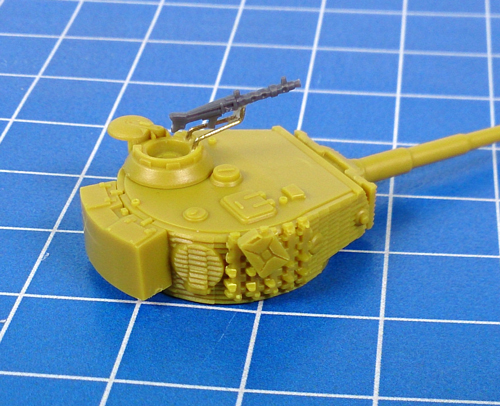
| Step 2. Next, I attach the jerry can on a slight angle directly to the spare track links. |
 |
 |
 |
What Is A Jerry Can?
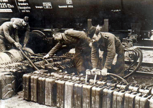
The Wehrmacht-Einheitskanister as it is known in Germany was developed in 1937 by Vinzenz Grünvogel, chief engineer at the Müller Engineering Company. Designed to specifically carry fuel for the military, this robust container was easy to carry and required no further accessories such as a funnel to pour. The container earned the nickname jerry can by the Allies during the Second World War as the term jerry was wartime slang for the Germans. Capable of carrying 20 litres (or 5.3 US gallons), a variation of the design was quickly adopted by the United States, the British and the Soviet Union.
Left: German soldiers busy filling 'jerry cans'. |
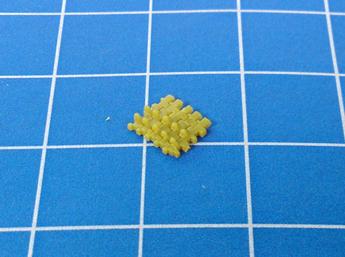
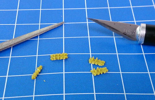
| To further add some interest to our Tiger I E, I decided to experiment with the spare track links included on the plastic Tiger I E frame. |
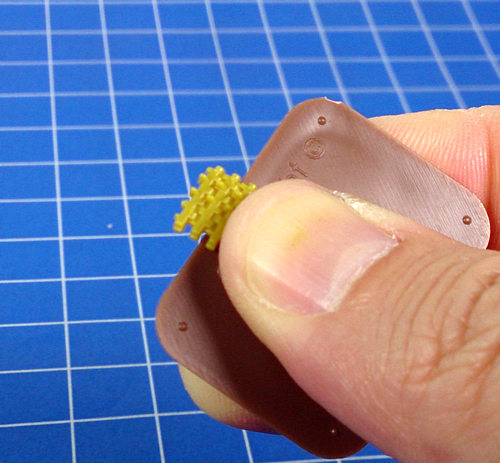
| Step 1. Here I use a small base to create the leverage I need to break off the spare links into sperate pieces. Tip: If you want two or more links this can be done simply using your fingers. If you want a single link, however, using a pair of needle nose pliers helps to get things started. |
 |
 |
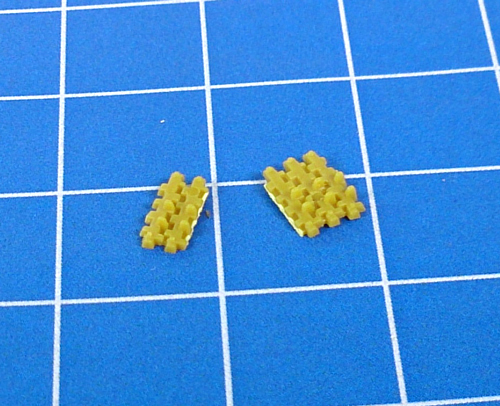 |
| Step 2. I then use a hobby knife and a hobby file to remove any leftover plastic between the teeth of the track links. |
 |
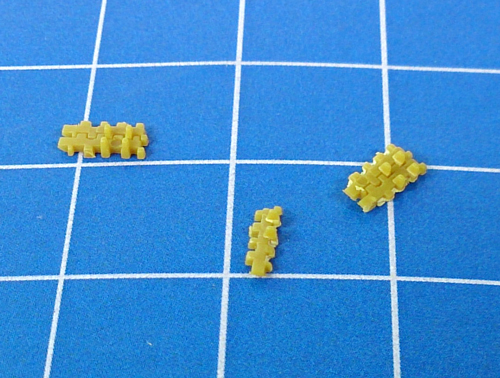 |
| Below: The left-hand side of the turret with a two-piece track section and a single piece. |
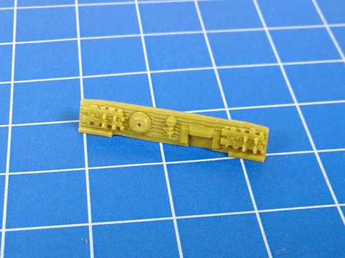
Below: The glacis plate with a pair of two-piece track sections adding a look of improvised armour. |
 |
 |
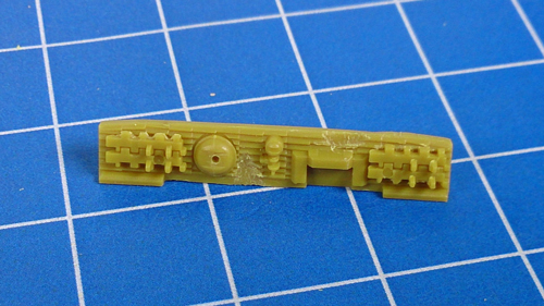
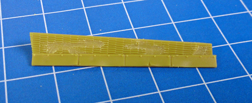
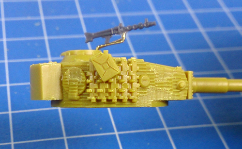
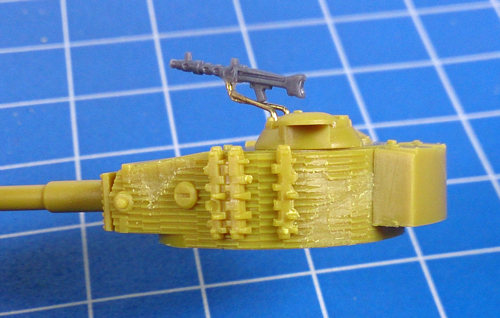
| Chipped Zimmerit |
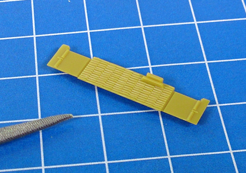
| If you want to add so real character to the Tiger I E then chipped Zimmerit is the way to go. If you look at any historical photos of the period, a majority of German tanks which had Zimmerit had some form of damage to this anti-magnetic coating. |
| Step 1. For Zimmerit chipping, I use the tip of a hobby file to scratch out the rough shape of the chipped section. |
 |
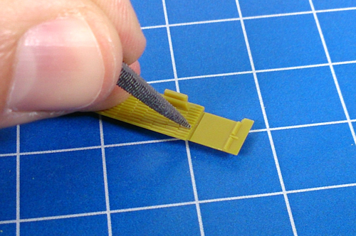 |
| Below: Scratching out the rough of a chipped section of Zimmerit. |
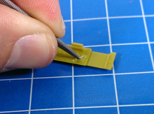
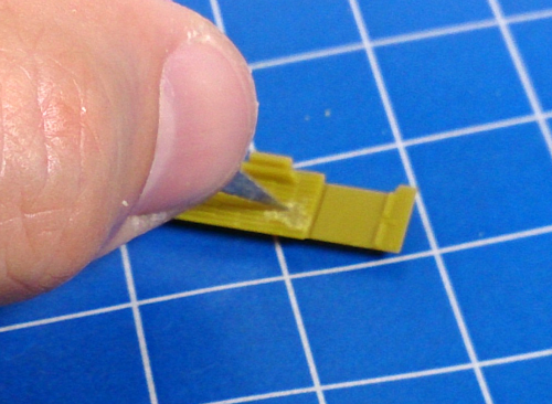
Step 2. I then use the tip of my hobby knife to refine the chipped section and tidy up any residual plastic. |
 |
 |
| Below: Two small chipped sections of Zimmerit on the glacis plate. |
Below: Chipped Zimmerit on the right-hand side hull section. |
 |
 |
| Below: Examples of the chipped Zimmerit on both side of my Tiger I E turret. |
 |
 |
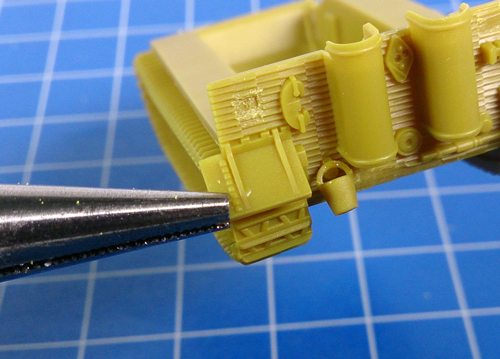
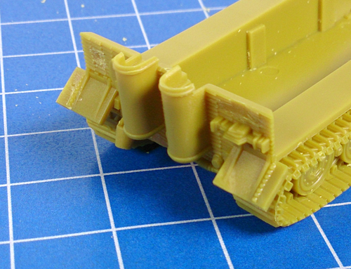
| Below: Bending up the rear mudguards. |
Below: The completed rear mudguards. |
 |
 |
Unit Insignia
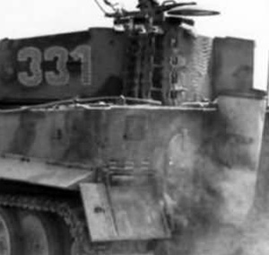
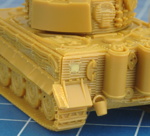
While creating my chipped Zimmerit sections, I also created a square patch on the left-hand side of the rear plate specifically for the unit insignia.
I then used some hobby putty to create a smooth surface to which I will hand-paint the insignia. Gulp!
Right and far right: The smooth section of Zimmerit where the unit insignia is located. |
 |
 |
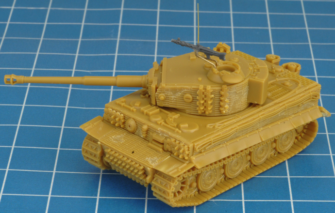
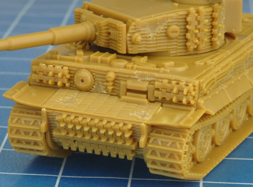
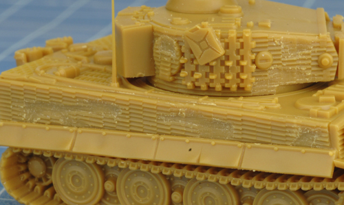
| My Fully Detailed Tiger I E |
 |
 |
 |
Join me in part three of A Tale of Two Tigers as I starting painting the Tiger I E.
~ Blake. |
|
|
|