|
|
|
|
Products mentioned in this Article
|
|
|
|
|
|
|
|
|
 |
|
|
 |
|
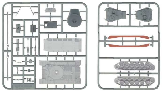
I'll begin construction of the M26 Pershing Platoon box set by demonstrating how to assemble the basic hull of the vehicle first using the components that are common to both the M26 Pershing and the T26E4 Super Pershing.
The components required to assemble the basic hull of the Pershing can be seen below highlighted in white on the sprues below. The components highlighted in red are optional.
|
| Assembling The Basic Hull (or the hull of M26 Pershing) |
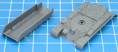
| Step 1. Begin assembly by joining the upper and lower hull sections. |
| Tip: Although regular Hobby Glue can be used to assemble plastic vehicles, we recommend that you use good quality plastic cement instead. It gives the strongest bond when gluing plastic to plastic. |
| Below: The lower hull section (left) and upper hull section (right). |
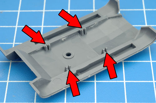
Below: Place a small amount of plastic glue to the tabs highlighted in the image below. |
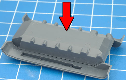
Below: Finally, bring the two hull sections together. |
 |
 |
 |
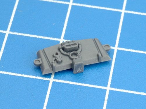
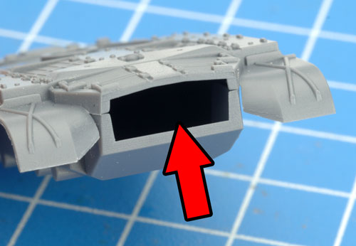
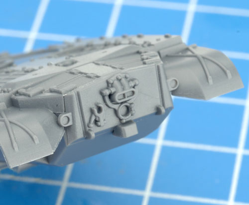
| Step 2. Next, attach the hull rear plate to the back of the hull. |
Below: The hull rear plate correctly attached to the hull. |
 |
 |
 |
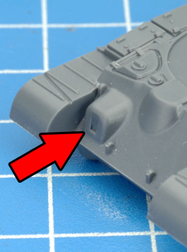
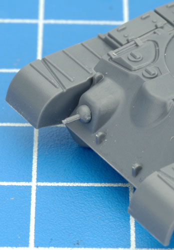
Step 3. Attach the hull machine-gun to the front of the hull.
Tip: As this component is quite small, a pair of modelling tweezers may aid you in attaching the hull machine-gun to the desired location on the front of the hull. |
Below: The hull machine-gun correctly attached to the front of the hull. |
 |
 |
 |
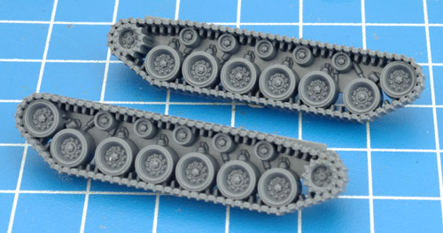
| Step 4. Next, attach the tracks to the hull. The tracks can be seen in the image below; the right-hand side track (top) and the left-hand side track (bottom). |
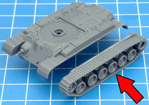
Below: Attach the left-hand side track to the hull. |
Below: The left-hand side track correctly attached to the hull. |
 |
 |
 |
| Tip: When referring to left or right-hand side in regards to a Flames Of War miniature, the orientation is determined as if looking at the vehicle from the rear. |
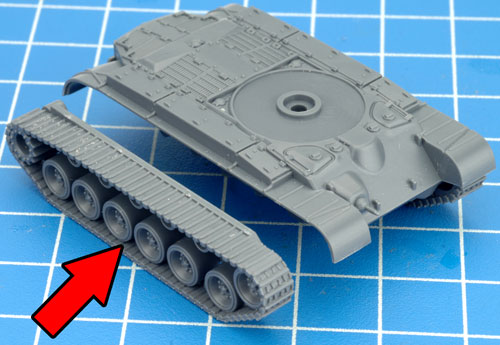
| Below: Attach the right-hand side track to the hull. |
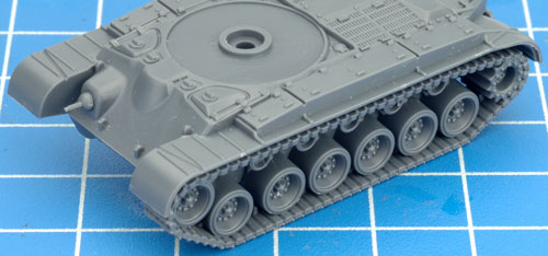
Below: The right-hand side track correctly attached to the hull. |
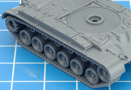
Below: With the tracks in place, the basic hull of the Pershing is now assembled. |
 |
 |
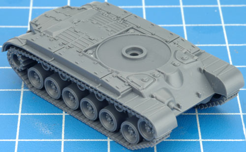 |
Note: This basic hull is also the correct hull used to represent the M26 Pershing in Flames Of War.
|
|
Adding The Optional Hull Components
The track fenders are an optional component that can be left off the vehicle during the assembly process if you choose to do so. Pershing crews would often remove these before going into action and the lack of any fenders on your vehicles will add some modelling variety amoungst your miniatures.
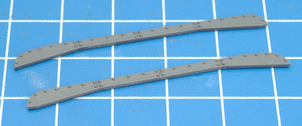
Below: The right-hand side track fender (top) and the left-hand side track fender (bottom).
|
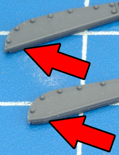
Below: The orientation of the track fenders is determined by the slightly angled-end as seen in the example shown at the bottom of the image. This angled-end points towards the front of the vehicle. |
 |
 |
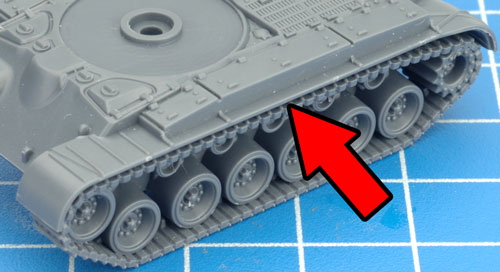
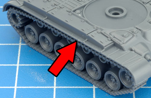
| Below: The track fenders attach to the underside of the lip between the upper hull section and the track itself. |
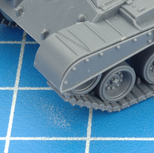
Below: A closer view of the correctly orientated left-hand side track fender. |
Below: The left-hand side track fender correctly attached to the side of the hull. |
 |
 |
 |
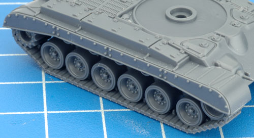
| Below: The right-hand side track fender correctly attached to the side of the hull. |
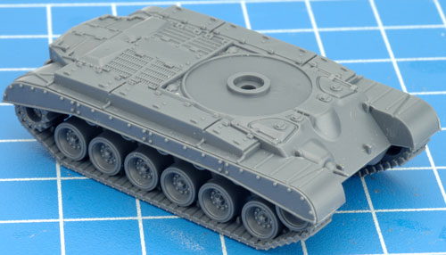
Below: The basic hull complete with the optional track fenders. |
 |
 |
 |
|
Modelling The T26E4 Super Pershing Hull
|
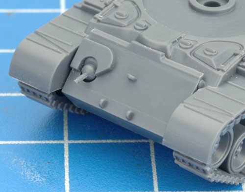
| The is only one difference between the basic hull of the M26 Pershing that we've just finished assembling and the hull of the T26E4 Super Pershing. This is the difference is the additional armour plate attached to the glacis plate. |
|
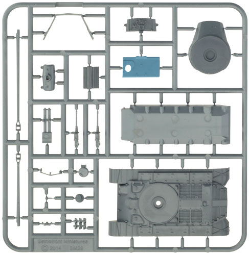
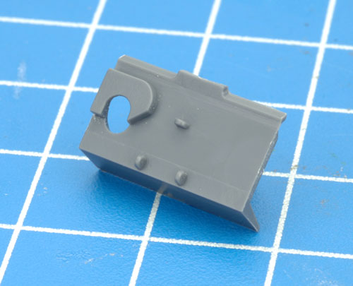
This additional armour plate can be seen highlighted in blue of the plastic Pershing sprue shown on the right.
Right: The additional armour plate highlighted in blue of the plastic Pershing sprue.
Far right: A closer look at the additional armour plate of the T26E4 Super Pershing.
|
 |
 |
| Assembling The The T26E4 Super Pershing Hull |
| Step 1. Follow the steps seen above to assemble the basic hull of the M26 Pershing. |
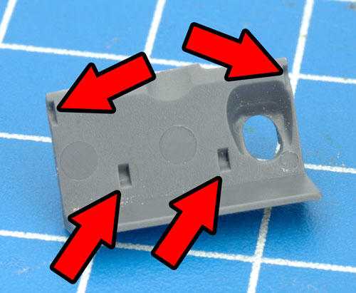
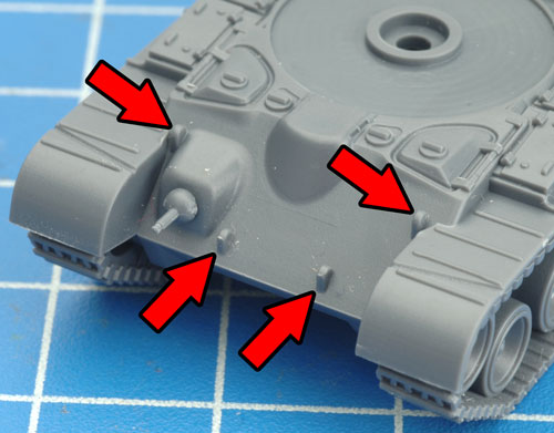
| Step 2. Next, place a tiny amount of glue in the recesses shown on the rear of the armour plate. |
Below: These recesses are partnered up with the raised detail of the glacis plate shown in the example below. |
 |
 |
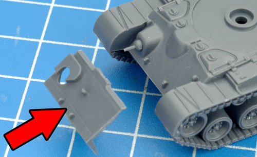
| Step 3. Attach the additional armour plate to the glacis plate of the hull. |
Below: The additional armour plate of the T26E4 Super Pershing attached correctly to the front of the hull. |
 |
 |
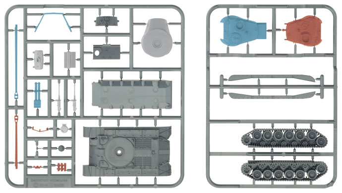
| Now that we have assembled both hulls types for the M26 Pershing Platoon box set, its now time to move onto the turrets. Highlighted below are the components required to assemble the turrets; the M26 Pershing highlighted in red; the T26E4 Super Pershing highlighted in blue and the components common to both turret types highlighted in white. |
 |
| Assembling The M26 Pershing Turret |
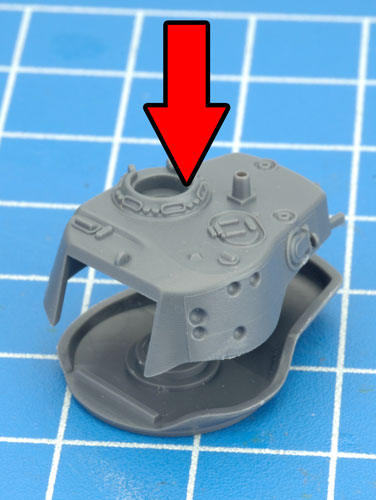
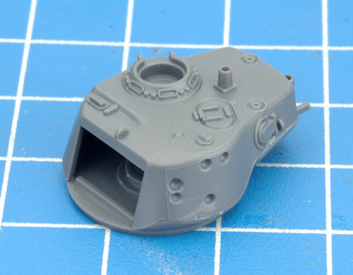
| Step 1. Begin assembly of the M26 Pershing turret by joining the upper and lower turret sections. |
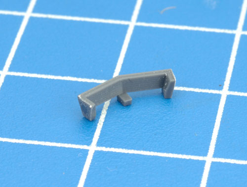
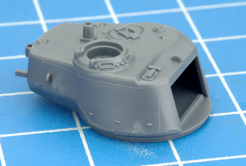
Step 2. Next, attach the turret stowage rack to the side of the turret. |
 |
 |
 |
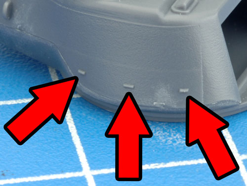
| Below: The side of the turret has three alignment guides to assist in the correct placement of the stowage rack. |
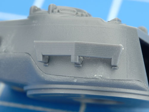
Below: A closer look at the stowage rack aligned correctly on the side of the turret using the guides. |
 |
 |
 |
| Below: Another view of the stowage rack correctly attached to the turret side. |
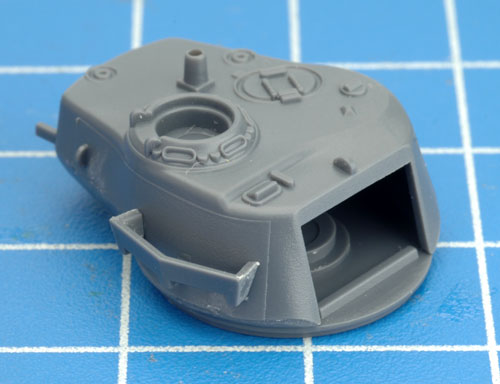
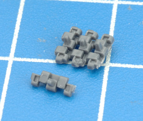
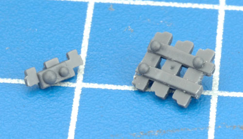
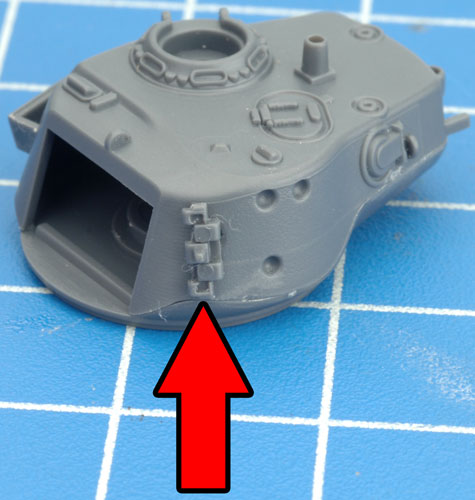
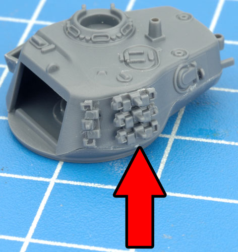
Step 3. On the opposite side of the turret are locations for two sections of spare track links.
Tip: The spare track links have been keyed along with the turret side to ensure correct orientation. See the examples in the images below. |
 |
 |
 |
| Below: The orientation guides for the spare track links on the side of the turret. |
Below: Attaching the spare track links to the side of the turret. |
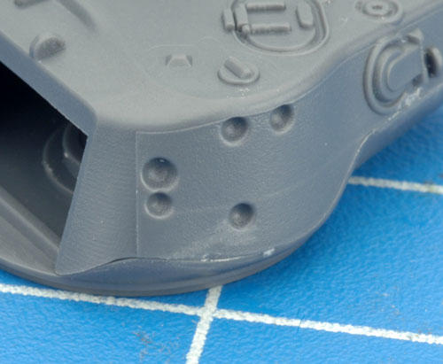
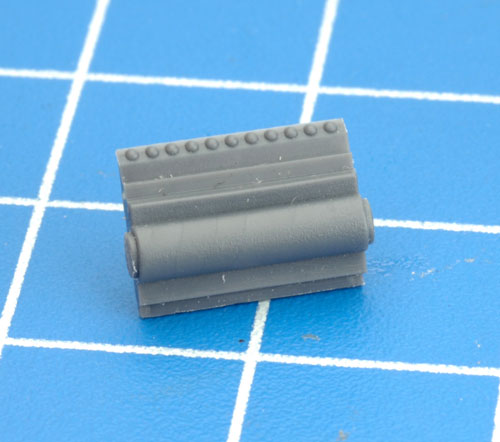
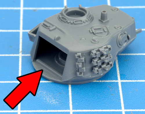
Step 4. Next, attach the gun mantlet rear plate to the front of the turret. |
 |
 |
 |
 |
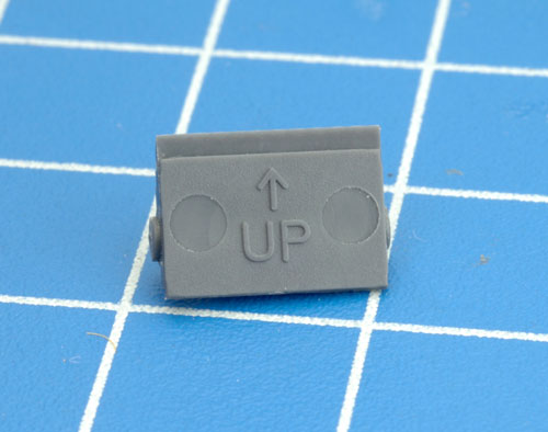
| Below: The back of the gun mantlet rear plate features the orientation mark 'UP' and an arrow to indicate which direction is up. |
Below: Attaching the gun mantlet rear plate to the front of the turret. |
 |
 |
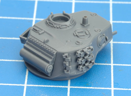 |
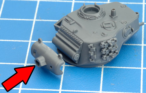
| Step 5. Next, attach the gun mantlet to the front of the gun mantlet rear plate. |
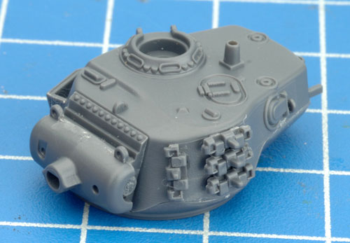
Step 6. With the gun mantlet in place, its time to attach the main gun. |
 |
 |
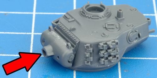 |
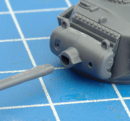
| Below: The end of the main gun has been keyed to fit with the recess located in the gun mantlet. |
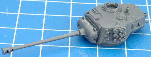
Below: The main gun attached correctly to the turret. |
 |
 |
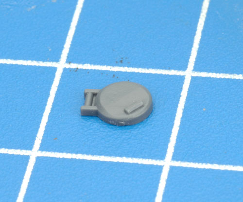
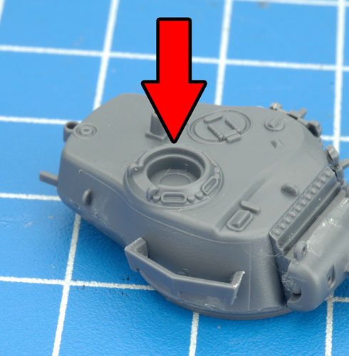
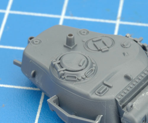
| Step 7. Next, attach the Commander's hatch to the top of the turret. |
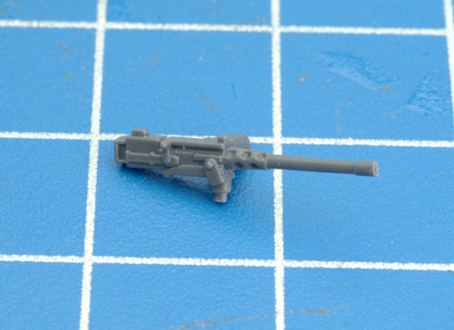
Step 8. Now it's ime to add the .50 cal AA MG. |
 |
 |
 |
 |
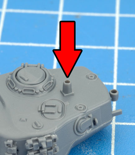
| Below: The .50 cal AA MG attached to the turret pintle mount located towards the rear of the turret. |
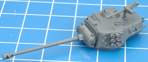
Below: With the .50 cal AA MG in place, the M26 Pershing turret is fully-assembled. |
 |
 |
 |
| Assembling The T26E4 Super Pershing Turret |
| Step 1. Begin assembly of the T26E4 Super Pershing turret by joining the upper and lower turret sections. |
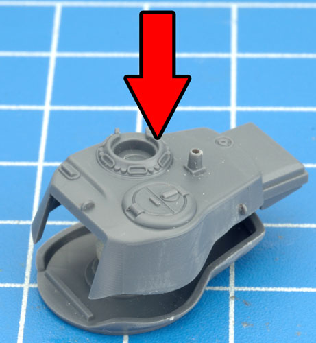
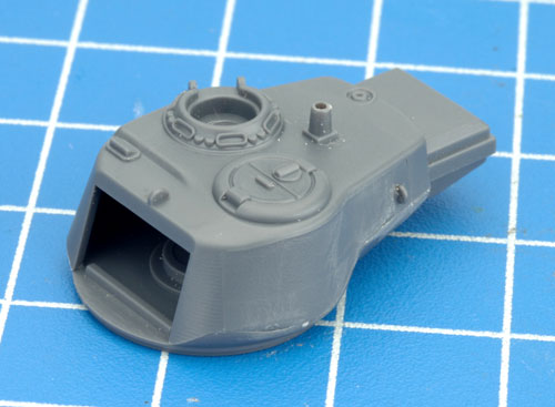
Step 2. Next, attach the gun mantlet rear plate to the front of the turret. |
 |
 |
 |
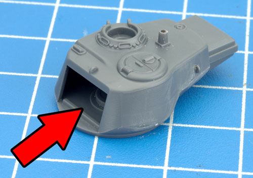 |
| Below: The gun mantlet rear plate correctly attached to the turret. |
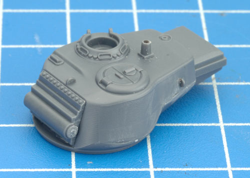
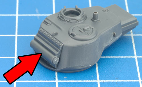
Step 3. Next, attach the gun mantlet to the front of the gun mantlet rear plate. |
 |
 |
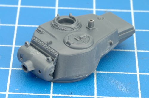 |
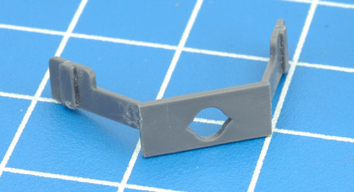
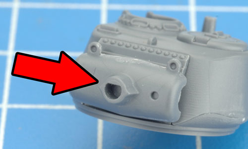
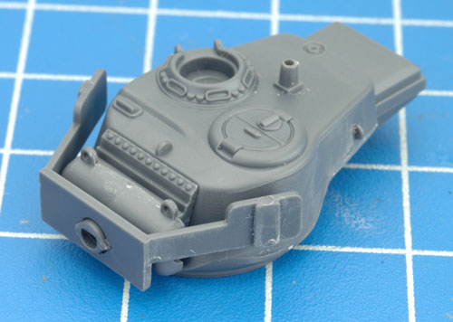
| Step 4. Once the gun mantlet is in place, the extra turret armour can be added. The extra turret armour simply slides over the nose of the gun mantlet. |
Below: The extra turret armour correctly attached to the gun mantlet. |
 |
 |
 |
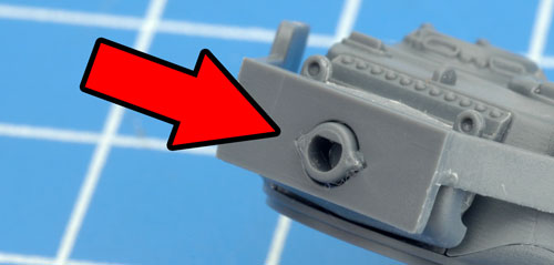
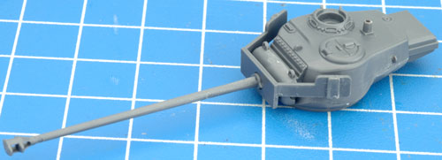
| Step 5. Next, attach the main gun to the gun mantlet. |
Below: The end of the main gun has been keyed to fit with the recess located in the gun mantlet. |
 |
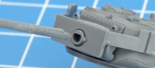 |
| Below: The main gun attached correctly to the turret. |
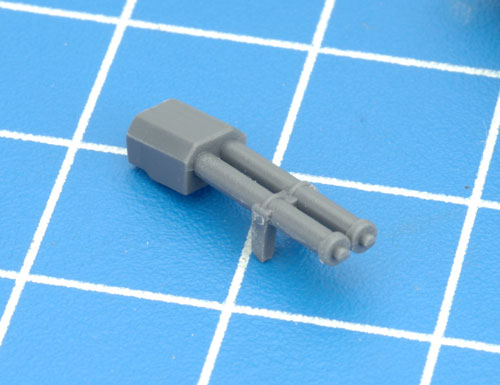
Step 6. Next, attach the external equilibrator springs to the top right-hand side of the turret. |
 |
 |
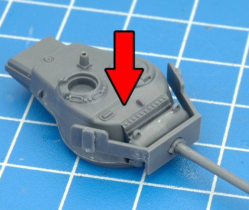 |
| Below: The external equilibrator springs attached correctly to the top of the turret. |
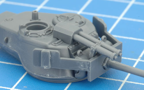
Step 7. Next, attach the Commander's hatch to the top of the turret. |
 |
 |
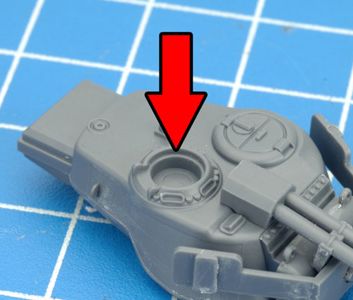 |
| Below: The Commander's hatch attached correctly to the top of the turret. |
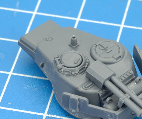
Step 8. Finally, attach the .50 cal AA MG to the turret pintle mount located towards the rear of the turret. |
 |
 |
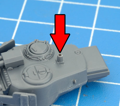 |
| Below: The .50 cal AA MG attached to the turret pintle mount. |
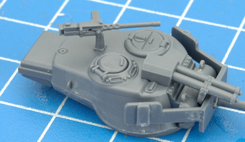
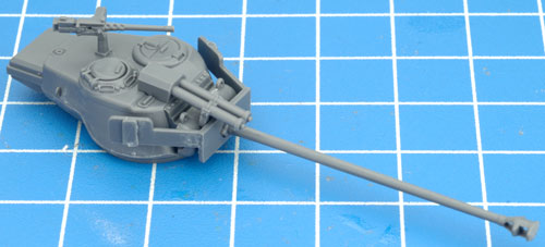
Below: With the .50 cal AA MG in place, the T26E4 Super Pershing turret is fully-assembled. |
 |
 |
| Attaching The M26 Pershing Turret To The Hull |
| Using The Turret Peg |
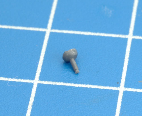
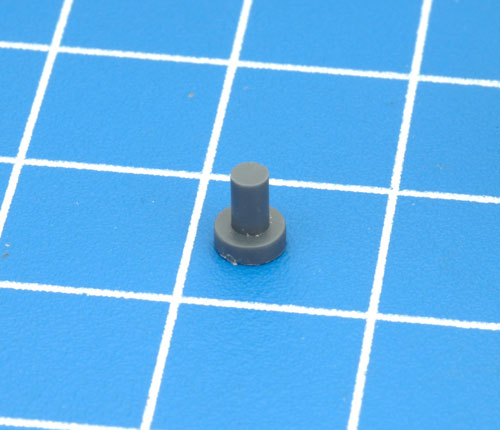
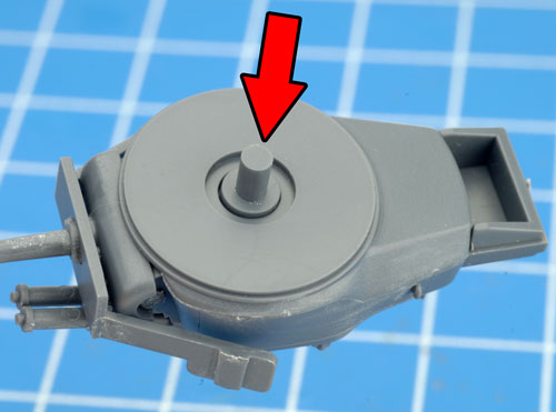
| A new addition to the M26 Pershing Platoon box set is the turret peg; see the image below. |
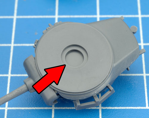
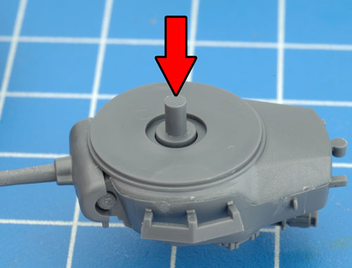
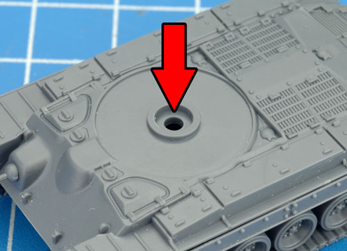
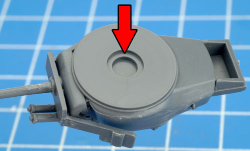
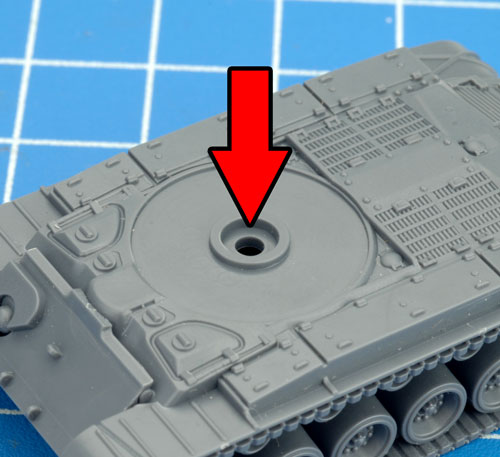
The turret peg simply attaches into the recess located on the bottom of the turret and plugs directly into the hole located on the top of the hull. |
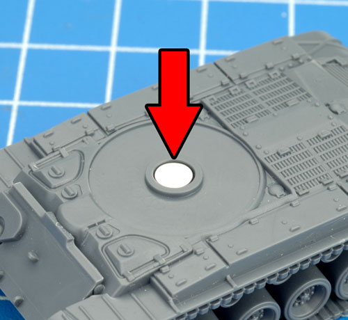
Below: The hole in the top of the hull that accommodates the turret plug. |
 |
 |
 |
 |
| Attaching The T26E4 Super Pershing Turret To The Hull |
| The new turret peg can be used on the T26E4 Super Pershing to attach the turret to the hull in exactly the same way as the M26 Pershing. |
 |
 |
 |
 |
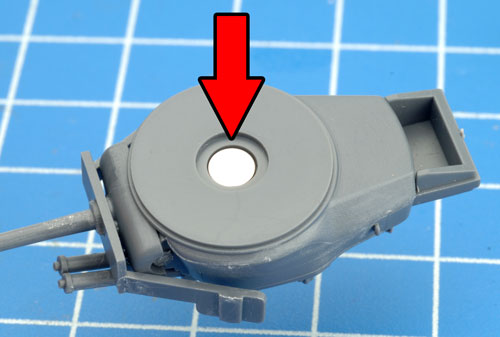
| Rare earth magnets can also be used to the turret of the T26E4 Super Pershing to its hull. |
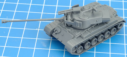
Below: With the turret attached using either the turret plug or rare earth magnets our T26E4 Super Pershing in now fully assembled. |
 |
 |
 |
I hope you find this assembly guide useful when it comes time to assemble your own M26 Pershing Platoon.
Happy modelling!
~ Blake. |
Last Updated On Friday, November 26, 2021
|
|
|