|
|
 |
|
|
Assembling the French Tank Combat Squadron
 |
Assembling the French Tank Combat Squadron
with Blake Coster
The tanks of France’s mechanised divisions have thicker armour and
bigger guns than the Germans, giving you a huge advantage in a
head-to-head fight. The German’s may try to out manoeuvre you, but they
can’t out run your armour-piercing shot!
Learn more about the French Tank Combat Squadron here...
|
The Contents
Firstly, let's take a look at the contents
of the French Tank Combat Squadron army box set; contact the Customer
Service team at [email protected] if you have any issues with any of the components. |
| The Somua S-35 The number in brackets indicates the number of each part contained in the box set. |
| The Hotchkiss H-35 & H-39 |
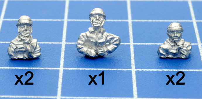
| Also included in the box set are six types of Command figures. Three command figures for the tanks (below): |
| And three command figures for the armoured cars (below): |
 |
This army box
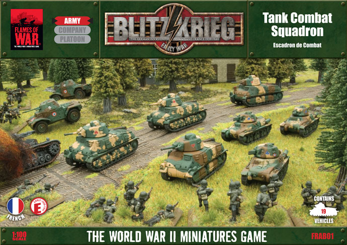
contains 19 armoured vehicles comprising of platoons of Somua S-35s and Hotchkiss H-35 / H39 tanks along with a platoon of Panhard AMD-35 armoured cars. Begin by taking your miniatures out of the box and sorting the
components so that you check that all the components are correct, once that’s
done you can begin cleaning up the components ready for assembly.
First, use a hobby knife and hobby files, to clean up any mould marks
and flash on the figure as much as possible. There are two things to
look for when cleaning up tanks.
Flashing and Mould Lines
Flashing is the large thin areas of metal that often form between the
Drive sprockets and the road wheels. Sometimes you will also get
venting which will be long stringy bits that hang off some of the track
sections. It’s very easy to remove this flashing either with a fine file
or a sharp knife.
Resin Bubbles
From time to time you will find a small amount of bubbling under
resin mudguards where the tracks connect to the hull of the tank. These
need to be carefully filled down so you can have a smooth join between
the Hull and the tracks.
For more details on preparing miniatures, read Mark's guide here...
Once you have cleaned up the components you can start assembling your miniatures. |
Assembling the Somua S-35
|
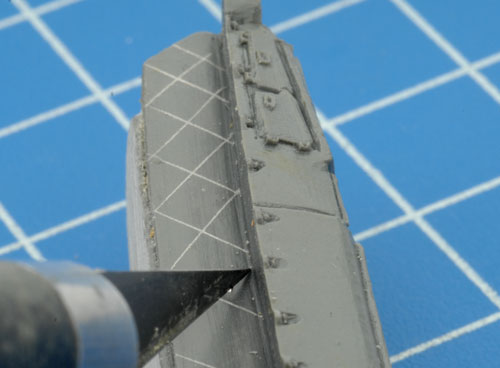
Before installing the tracks onto the resin hull, score the track recess area with your hobby knife.
|
 |
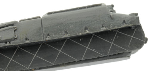 |
This gives the glue something to adhere to, creating a better bond between the resin hull the the metal components. |
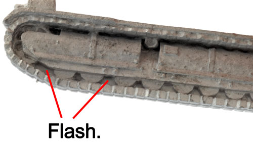
| Before attaching the tracks, insure that you've removed all of the flash between the road wheels. |
|
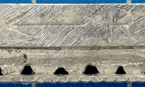 |
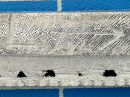
Each track is marked with an arrow showing which end of the track faces forward. Each track also has either a R or a L indicating which side of the tank it belongs when looking at the resin hull from behind.
In this example, we see the right hand track of the Somua S-35. |
And here is the left hand track with it's markings.
|
 |
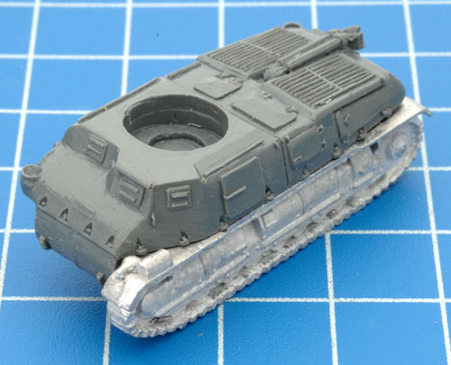 |
Now that we've correctly indentified which side each track belongs, we can glue them to the resin hull.
|
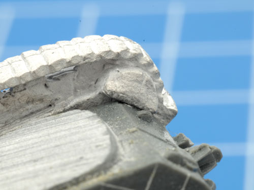
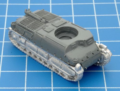
To ensure that the track is centred on the resin hull, each track has a metal tab at it's rear.
You should ensure that this tab is flush with the end of the resin hull as shown in the example to the right. |
 |
 |
Once both tracks have been attached to the resin hull, its time to move on to the stowage bins.
|
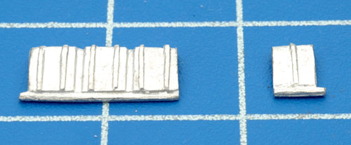
The stowage bin are optional for the Somua S-35, so feel free to add them or leave them off or a combination for modelling variance across your units.
|
 |
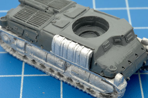 |
Here is an example of the full set of stowage bins attached to the resin hull.
|
And here is the single stowage bin attached to the resin hull.
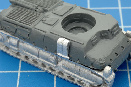
With the construction on the hull now complete, it is time to move onto the turret.
Tip: You can use rare earth magnets in all of the vehicles featured in this article.
Learn more about using rare earth magnets here... |
 |
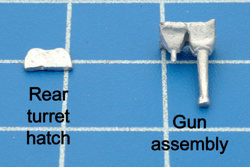 |
The metal components of the turret include the Rear Turret Hatch and Gun Assembly shown in the example on the left.
Note: The third part on the sprue along with Rear Turret Hatch and Gun Assemly is a piece for the Char B. It is not used with any of the models in this box set.
|
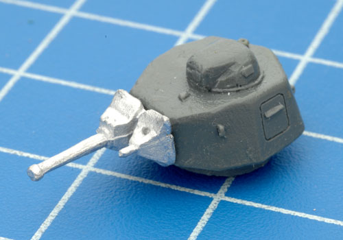
| The Gun Assembly plugs into the front of the resin turret. When attaching the gun, ensure the Co-ax MG is on the left of the main gun (when viewing the turret from behind ) as shown in the example to the right. |
 |
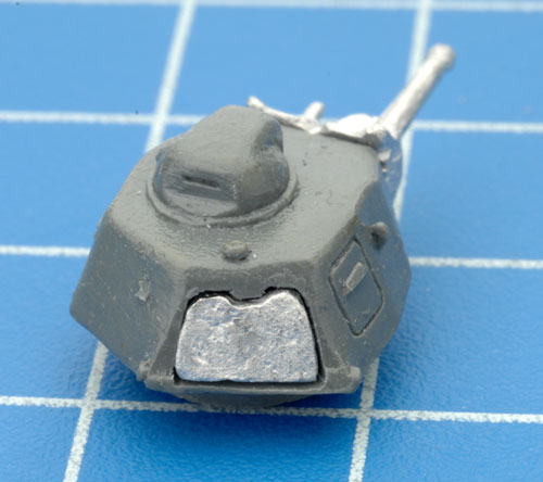 |
The rear hatch simply sits in the recess in the back of the turret. |
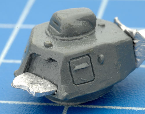
Like the stowage bins, the rear turret hatch also provides an opportunity for modelling variance.
The hatch can be modelled in the open position as shown here or with a command figure and, of course, in the closed position. |
 |
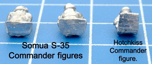 |
The command figures for the Somua S-35 have a different shaped based compared to the Hotchkiss command figure.
Refer to the examples to the left for more details.
|
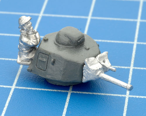
| Simply replace the rear turret hatch with your choice of Somua S-35 command figure. |
 |
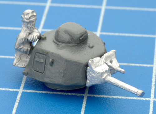 |
The second variant of the Somua S-35 command figure in place. |
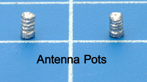
The other components to add to the Somua S-35 if your planning on constructing a command vehicle is the Antenna Pots.
Note: The antenna pots are only for command vehicles and the box set comes with twenty nine of these antenna pots. |
|
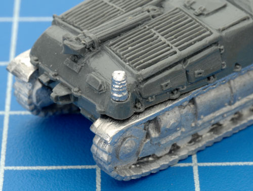 |
Shown here is the position of the rear antenna pot on the Somua S-35. |
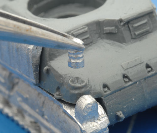
Here is the position of the front antenna pot.
Getting these parts in the correct position can be tricky, using a set of hobby tweezer will aid in this task. |
 |
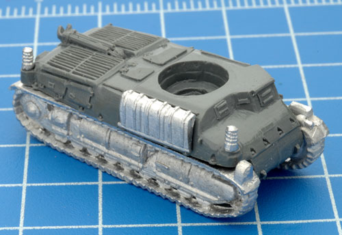 |
Both antenna pot attached correctly to the resin hull.
|
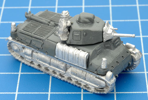
A completed command Somua S-35.
|
 |
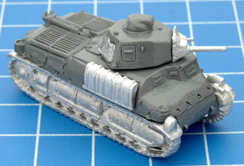 |
A completed regular Sumoa S-35. |
| Assembling the Hotchkiss H-35 / H-39 |
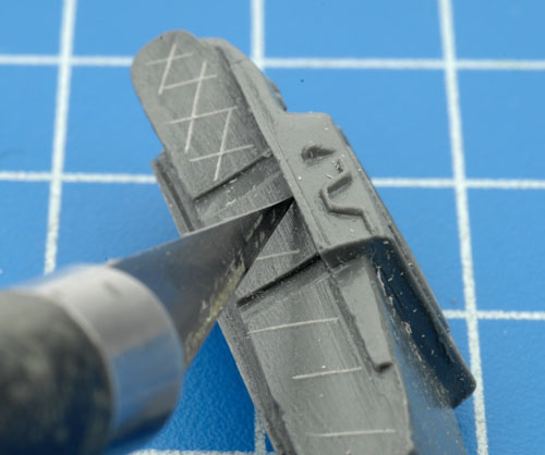
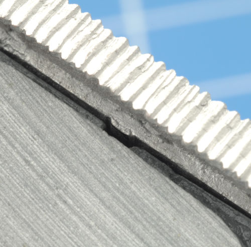
It is a good idea to also score the resin hull of the Hotchkiss before attaching tracks.
|
 |
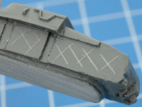 |
Once again, your hobby knife is perfect for this task.
|
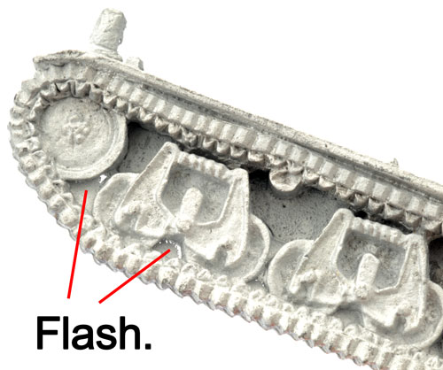
Be sure to remove the flash between the road wheels of the tracks before attaching them to the resin hull.
|
 |
Unlike the Somua tracks, the tracks on the Hotchkiss have metal lugs on the tracks and matching recesses in the resin hull to ensure correct orientation. Below are examples of the left Hotchkiss track and the left hand side of the resin hull.
|
Here is the right hand side of the resin hull the matching right hand track.
|
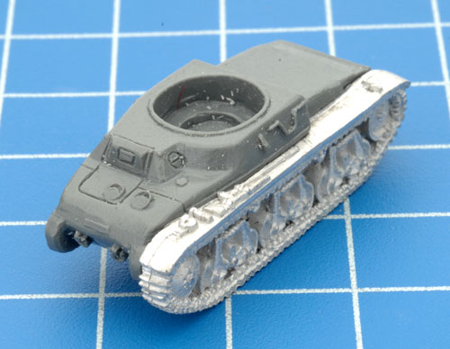 |
Once the correct side alignment for the tracks has been determined, the tracks can now be attached to the resin hull.
|
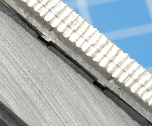
Here, you can see an example of the correctly aligned metal lugs and the recesses on the left hand side.
|
 |
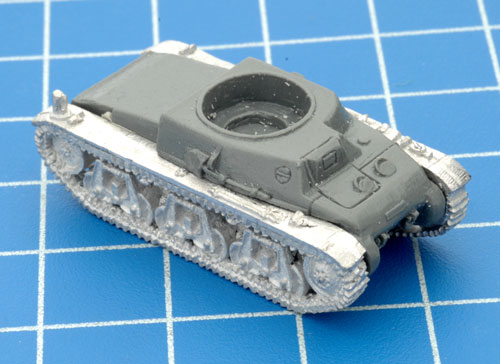 |
Both track successfully attached to the resin hull.
|
Correct alignment has also been achieved on the right hand side of the vehicle.
|
 |
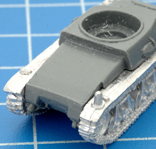 |
With the tracks attached, its time to complete the hull by adding the engine deck.
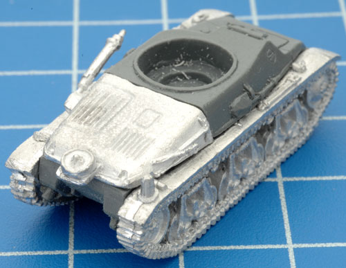
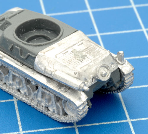
The engine deck is what determines if the tank is going to be a Hotchkiss H-35 or a Hotchkiss H-39.
Below are examples of both versions engine deck.
|
If your still finding it hard to tell the two apart, Evan had labeled each one on the underside. See the examples below:
|
When attaching the H-39 engine deck, the exhaust pipe sticks out at the wrong angle.
A soft touch is needed to bend it into the correct position. A little downwards pressure is needed to gently bend the exhaust pipe towards the hull.
See the examples below for further reference.
|
 |
 |
The H-39 engine deck is a lot less fuss to attach. A little hobby glue and you're done.
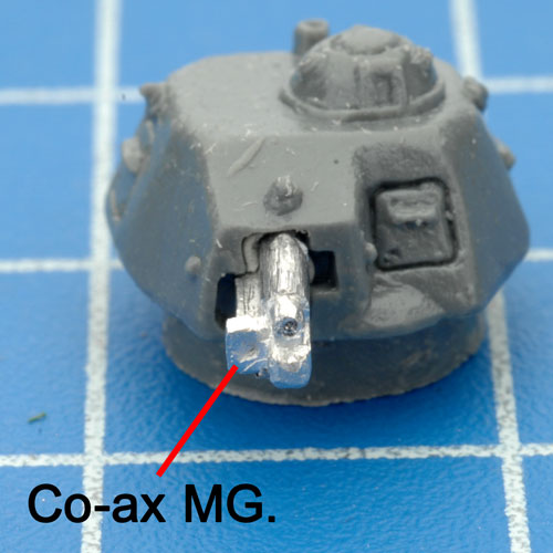
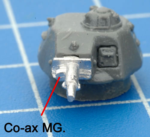
With hull assembly completed, it is time to move onto the turret. Like the hull, the two options. This time with the gun, either a long barrel 37mm gun or a short barrel version.
See the examples below. |
First the short barrel version. This simply plugs into the recess at the front of the turret.
Make sure the Co-ax MG is aligned as shown in the example on the right. |
 |
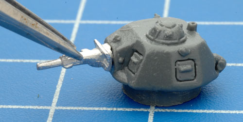 |
Since both guns are quite small, using a pair of tweezers will greatly aid your cause.
|
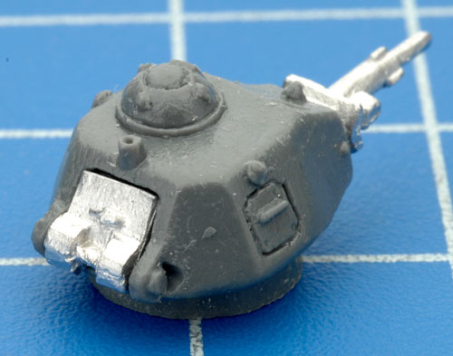
Like the short gun gun, make sure you the Co-ax MG on the long barrel is aligned as shown in the example on the right.
|
 |
 |
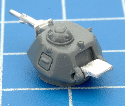
Next is the rear turret hatch, this simply plugs into the recess in the back of the turret. |
The rear turret hatch also provides opportunity for some modelling variation. In this example, the hatch it open.
This can be done by applying a small amount of hobby glue to the base of the hatch recess.
|
 |
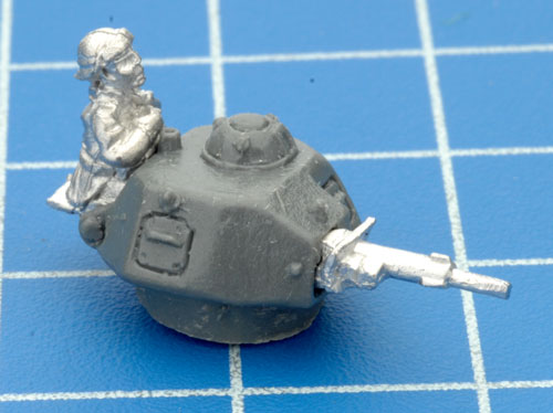 |
If creating a command vehicle, you can also add a command figure.
|
Remember, the Hotchkiss command figure has the square base as seen when compared to the command figures of the Somua S-35.
|
 |
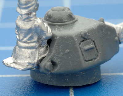 |
The command figure simply plugs into the hatch recess as shown in the example to the left.
With the Hotchkiss, there are many different combinations that you can create. A H-35 or a H-39, short barrel or long barrel gun, open or closed hatch, added command figure etc.
Below are a few examples. |
Assembling the Panhard AMD-35
|
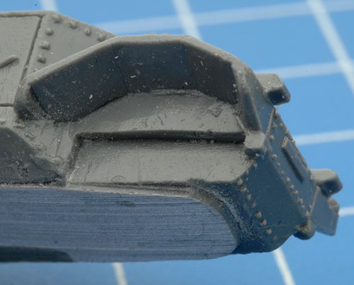
| The wheels of the Panhard are univeral i.e. it doesn't matter which wheel goes in what position in the resin hull. |
 |
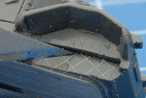 |
Again, it is a good idea to score the recess with your hobby knife before attaching the wheels.
|
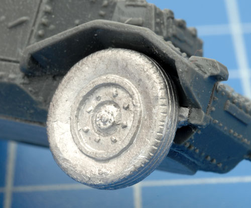
Each wheel should fit nicely into the recess in the resin hull.
|
 |
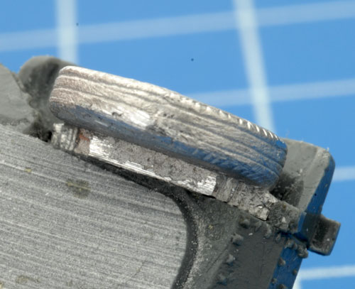 |
The example to the left show the correct alignment of a wheel in the resin hull.
Attach the all the wheels to the resin as shown in the examples below.
|
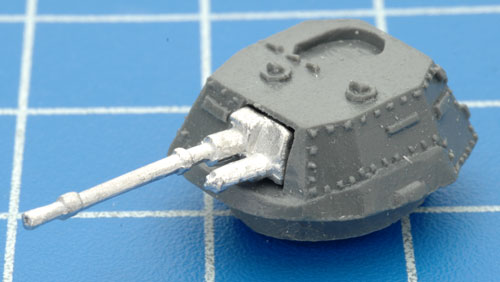
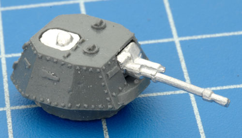
Time for the turret. The gun plugs into the recess in the front of the turret, this time with the Co-ax MG aligned as shown in the example on the right.
|
 |
 |
Next is the turret hatch, this simply sits in the recess in the top of the turret and is aligned as shown in the example to the left.
|
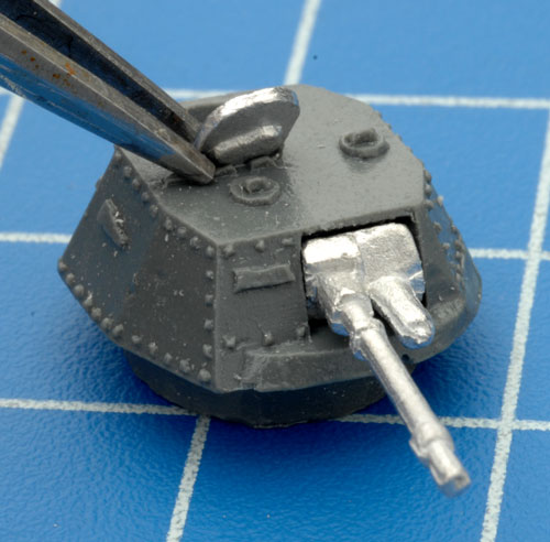
If you decide to add a commander figure, you'll need to model the hatch in an open position.
On the Panhard, the turret hatch opens towards the front. With the aid of tweezers and a little hobby glue at the base of the hatch this can easily be achieved. |
 |
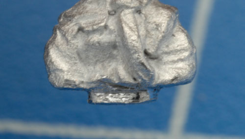 |
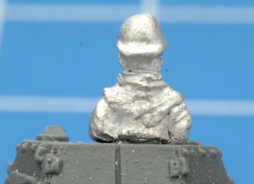
Choose one of the Panhard command figure but when trimming the stem off the bottom of the figure leave a small amount equal to the depth of the hatch recess in the top of the turret. |
The goal is to have to command figure sitting flush with the top of the turret as shown in the example to the right.
A small amount of hobby glue on the base of the stem and on each side of the turret where the command figure's arms rest will ensure an excellent bond. |
 |
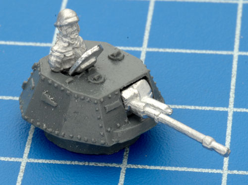 |
The completed turret with open hatch and command figure.
|
Like the Sumoa S-35, when creating a command Panhard the antenna pots need to be added to the vehicle.
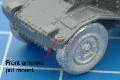
The position for the front antenna pot is shown on the right. |
 |
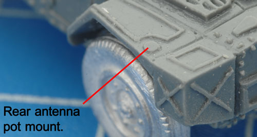 |
And here is the position for the rear antenna pot.
|
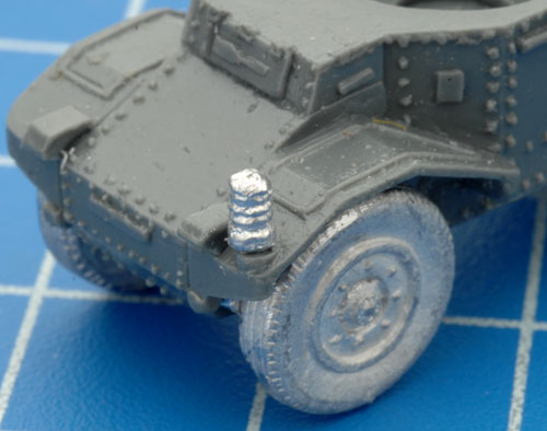
The mounted front antenna pot.....
|
 |
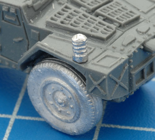 |
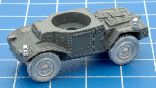
.....and the mounted rear antenna pot.
|
| With both antenna pots in the correct position the Panhard is nearly complete. |
 |
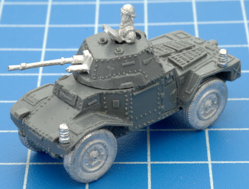 |
With the addition of the turret, the command Panhard in now fully assembled.
|
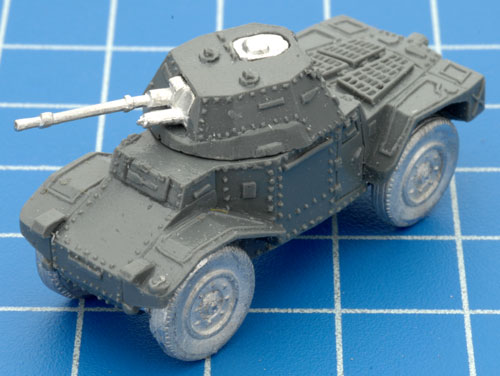
| Minus the open hatch, command figure and antenna pots. Here is the completed regular Panhard. |
 |
Want To Know More About Blitzkrieg?
Over the past few months we have added a massive range of articles
about Blitzkrieg to the website, to make it easier for people to find a
specific article we have put together this handy place.
Find out more about Blitzkrieg and Early-war here...
|
|
|
|