|
|
|
|
Products mentioned in this Article
--None--
|
|
|
|
|
|
|
|
|
 |
|
|
 |
Modelling the Antenna Array: Part Two
BP 44 Armoured Train Infantry Car
with Blake Coster
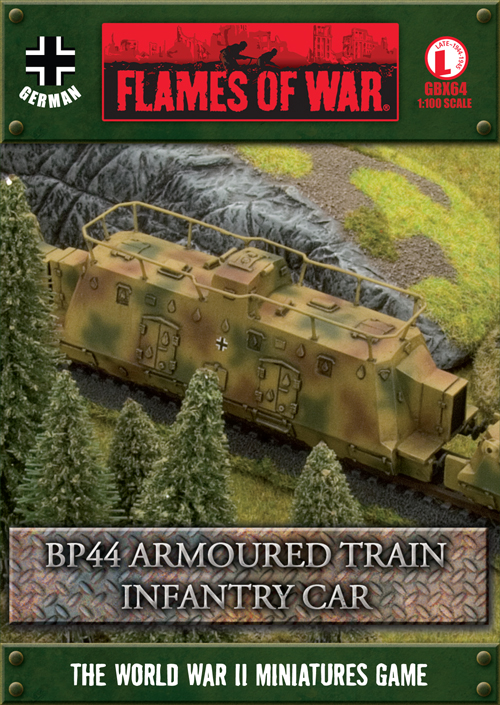
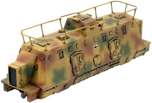
The new German BP44 armoured train is an exciting, new model that can be fielded in Flames Of War by using Grey Wolf: Axis Forces on the Eastern Front, January 1944 – February 1945. The Armoured Infantry Car is a vital part of the armoured train; either as protection for the infantry platoon carried within or as the Staff car for the artillery that arms the train. One of the most important (and coolest) features on the Infantry Car model is its antenna array. In this article, I will show you how to model the wire frame antenna array on the infantry car.
Learn more about the BP44 Armoured Train Infantry Car here...
|
Grey Wolf
Grey Wolf represents the Axis forces (Germans, Hungarians and
Finns) serving on the Eastern Front between January 1944 and February
1945.
Learn more about Grey Wolf here... |
 |
The Wire Frame Antenna
This by far is the most challenging modelling wise of the antenna array options. But I personally feel that it looks far cooler and it is the most robust option. If you not feeling totally confident in your modelling skills, then check out part one of this article for more options in regards to the antenna array.
Read part one of the Antenna Array article here…
Right: The Armoured Infantry car with my wire frame antenna array.
|
 |
| Tools Needed For The Job (Click on the links below to view each item in the online store.) |
Modelling the Wire Frame Antenna Array
Step One: Replacing the Antenna Poles
Since I will be soldering the joints on my wire frame antenna, I need to replace to antenna poles included in the Infantry Car box set. This is where the GF9 pinning refill kit comes in.
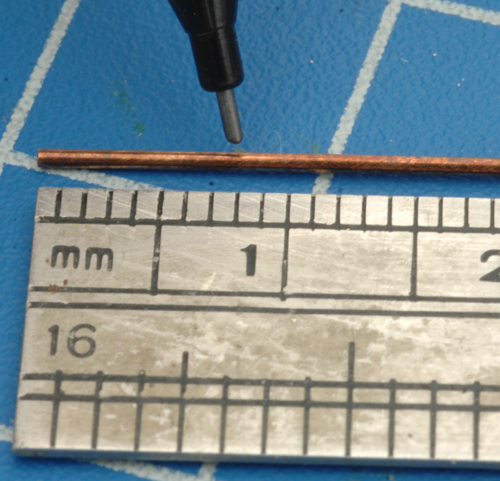
Using the thinner of the two gauges provided in the refill kit; begin by measuring and mark-off an 8mm piece.
Right: Measuring and marking off an 8mm piece of pinning rod. |
|
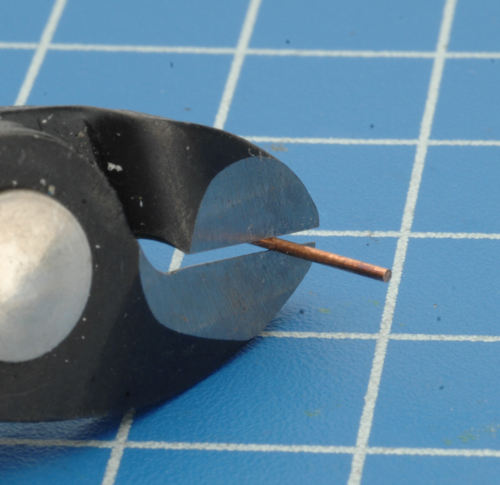
| Next, use a pair of GF9 heavy duty cutters to cut the length of pinning rod. |
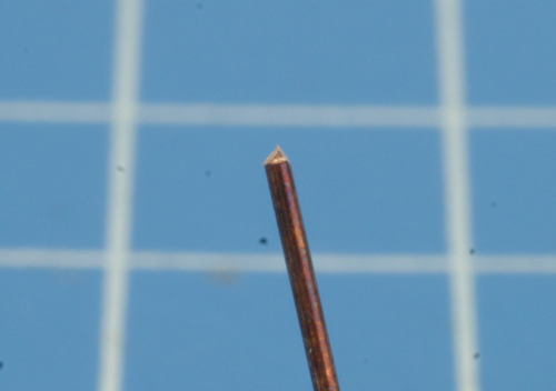
After cutting off piece the pinning rod, the end of the rod will be burred. |
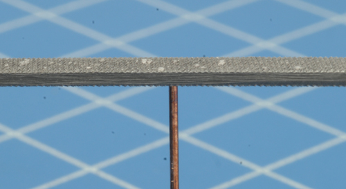
We need both ends to be square; use a flat file from the GF9 file set to tidy up and square of each end.
|
 |
 |
 |
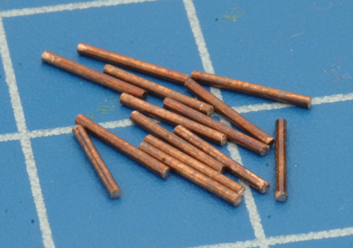 |
Repeat the process till you have 14 pieces of pinning rod cut and squared off.
Left: The 14 piece of pinning rod ready for the next step.
|
|
Step Two: Attaching the Antenna Poles
|
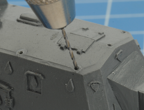
| Using the pin vice included in the GF9 model pinning system and the small drill from the refill kit; quickly tidy up
any of the holes you feel need it. |
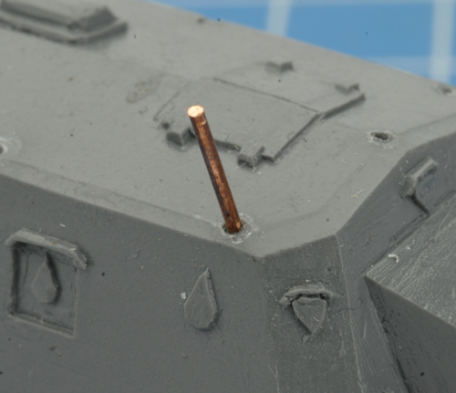
With a small amount of GF9 hobby glue insert a piece of pinning rod into each of the holes. |
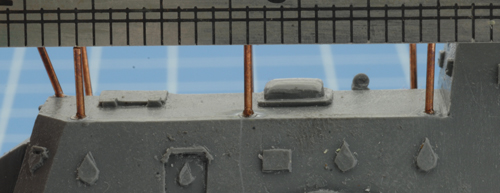
You may need to make some small adjustments to achieve height and alignment.
Tip: Use a straight edge to ensure the pinning rod is at the same height. |
 |
 |
|
|
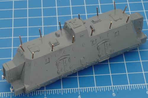
Once the process is complete, you should end up with something that looks like the example shown in the photo on the left.
Left: All 14 pieces of the pinning rod secured into place on the Infantry Car. |
Step Three: Creating the Antenna
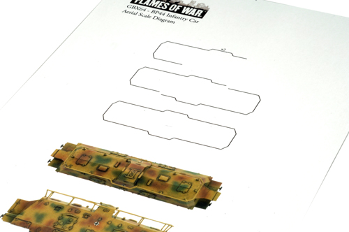
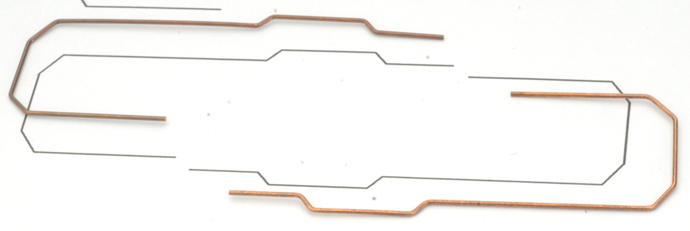
I asked Sean to create a template for the antenna array. This will save
to the trial and error I went through when first creating the antenna array for my armoured train.
|
|
Download a PDF version of the antenna template here...
IMPORTANT: In the Print options, under Page Scaling make sure you select None before printing the template.
|
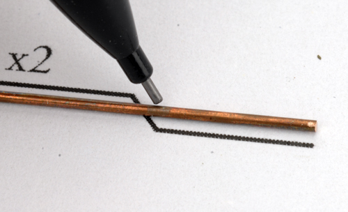
With a new piece of pinning rod (the same gauge as the antenna poles), use the template to mark where the bend needs to be. |
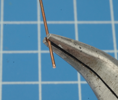
Using a pair of GF9 needle nose pliers, align the pinning rod with the mark on the inside of the jaws of the pliers.
|
 |
 |
 |
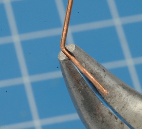
Then, use your thumb to gentle bend the pinning rod to the desired angle.
|
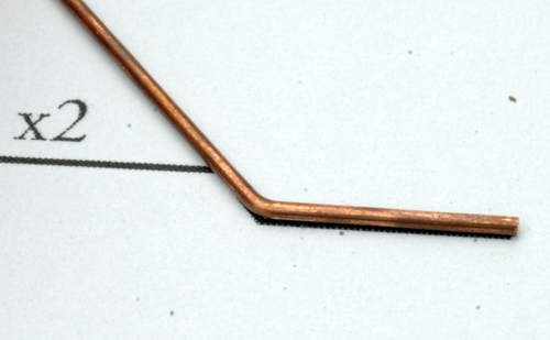
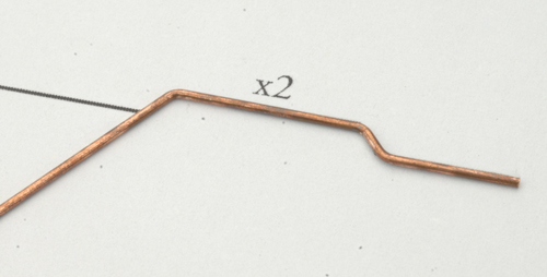
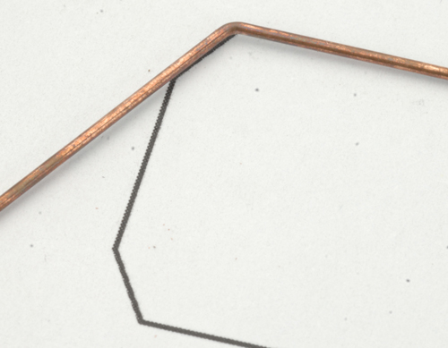
Next, compare the bend to the template to ensure it is correct.
|
Keep marking, bending and comparing for all the bends in the antenna.
|
 |
 |
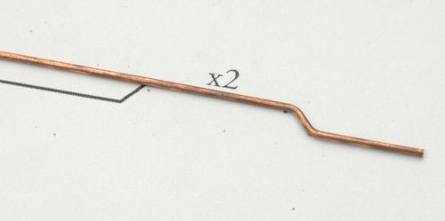 |
| As you go, you may need to make a few small adjustments here and there but with a little patience you'll get there. |
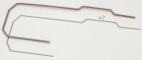
Once the bends are completed and your happy with the outcome, trim off any exist rod and square off the ends with your file. |
 |
 |
|
| Once you've completed one side of the antenna array, repeat the process to create the other half. |
 |
| Step Four: Attaching the Antenna |
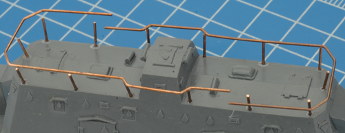 |
How it's time to attach the antenna array to the antenna poles.
Begin by tacking the two pieces of the antenna to the antenna poles near the housing in the middle of the infantry car. Be sure to use only a very small amount of hobby glue.
Left: Tacking the antenna into place.
|
|
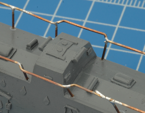
Begin soldering these joints and slow work your way around the entire antenna. As you go you may need to make some adjustments to align everything correctly, but with a little patience you should be able to achieve a good result.
If you've never soldered before, the link below provides an excellent tutorial. It focuses on electronic components by the same principles apply.
Learn how to solder here...
Right: A close up of the the soldered joints.
|
 |
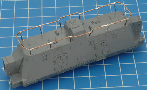 |
Once all of the joints are completed and you're happy with them, use a round file to tidy up the joints.
Tip: Apply a small amount of hobby glue around the base of each of the antenna poles to further reinforce the entire antenna structure. |
|
With the antenna in place and the jointsnice and tidy, the infantry car is ready to be painted.
~ Blake.
|
Last Updated On Thursday, March 15, 2012 by Blake at Battlefront
|
|
|